With this video guide you will be able to learn how to deploy demo version of the safety critical bootloader on SAMV71Q21. For this purpose we use standard automotive COSTS development board from Microchip: SAM V71 XPLAINED ULTRA. The only additional item you will need is a UART dongle which is used for exchange of PUS-C TC/TM allowing to command the bootloader and flash target application software image. You can get the demo version directly on our product download page.
Hardware Setup
- Development Board: Use the SAM V71 Xplained Ultra.
- UART Connection: Connect a USB-to-UART dongle to the board. This handles the PUS-C Telecommand (TC) and Telemetry (TM) exchange. In our lab we use dongles based on FT232.
- Debug Link: Connect the on-board EDBG USB port to your PC for initial flashing.
Chip Erase
In the fist step you need to ensure that internal Flash memory is erased.
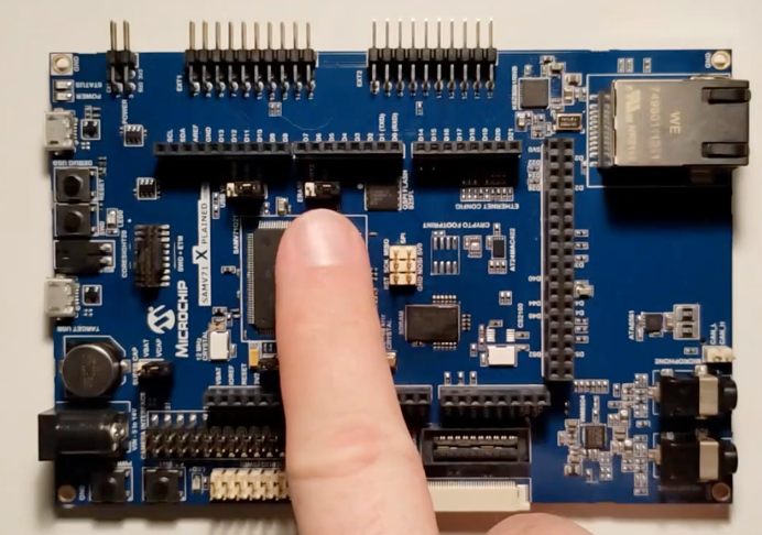
- Power off the board: Unplug the USB power cable.
- Connect ERASE jumper: Set PB12 jumper to ERASE position.
- Power on the board: Plug in the USB power cable.
- Wait 10-15s.
- Power off the board: Unplug the USB power cable.
- Disconnect ERASE jumper.
- Power on the board: Plug in the USB power cable.
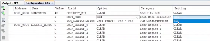
Ensure the correct GPNVM settings
GPNVM bit 1 selects boot mode for the MCU. After erase peration it is reset to boot from ROM. It needs to be se to 1 to force boot from internal Flash. Some debuggers do this sutomatcially when loading image to flasg (e.g. Segger).
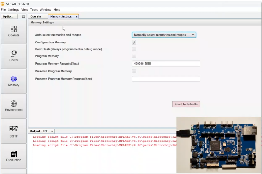
- Launch MPLAB IPE.
- Switch to advanced mode: Settings -> Advanced Mode. Default password is: microchip.
- Switch to memory settings: Memory settings tab on the left. Select: “Manually select memories and ranges” uncheck Boot Flash and Program Memory.
- Configuration Bits: Go to Window -> Target Memory Views -> Configuration Bits.
- Read configuration: Go to Operate tab and select Read.
- Ensure bit 1 is set.
- Write configuration memory.
Upload BSW in MPLAB IPE
Now you are ready to upload N7 Space bootloader into flash memory.
- Change memory settings: Go to memory tab on the left and select Program memory check box.
- Select hext file: Go to Operate section on the left and select n7s-bsw-demo hext file by browsing file system.
- Program file: Click program.
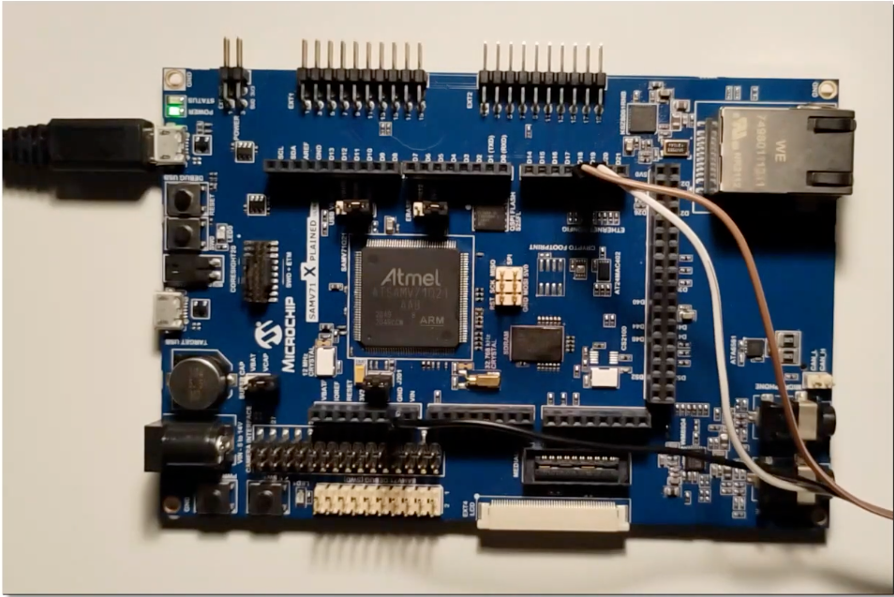
Connect UART dongle
You need to connect extarnal UART dongle as the interfece provided by USB cable is subject to resets on power toggle.
- Power of the board: Unplog USB power cable.
- Connect UART dongle: RX to D18, TX to D19, Ground to GND.
- Program file: Click program.
Uploading application software with BSW
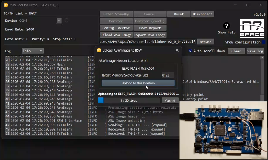
In this section we will use supplied N7S-BSW-Tool to communicate with BSW and upload custom application software.
- Lanuch N7S-BSW-Tool-v2.0.0: In window BSW Tools: Configuration select DEMO – SAMV71Q21.
- Select COM port: Under device section select your COM port used for the connected USB congle. Make sure that the selected port is correct.
- Enter standby: Click Enter Standby.
- Power cycle or reset the board: Bootloader will sutomatically swith to Standby Mode and await further transmission over PUS-6.
- Select application image: Browse files and select n7s-asw-led-bliker file.
- Upload application: Click Upload ASW Image and confirm.
- Send reset TC: Click Reset button.
After reset BSW will automatically wait 30s for possible comanding and then launch uploaded application image. LED should blink.